Harder Better Faster Stronger Box
May 29, 2023 | Author: Nic La | Tags: project code microcontroller boxA Daft Punk inspired musical puzzle box. Each of the silicone push buttons in the 4x4 grid delivers a soundbite from Daft Punk's hit song "Harder, Better, Faster, Stronger". The player must deliver these soundbites in the correct order to unlock the drawer and receive the prize. The correct order being found in the later half of the song. The prize being this year's nonfungible denomination, the celebratory $100 bill.
WARNING: My puzzle boxes do not come with instructions for the player. The player is meant to figure out the rules to the game as well as complete the game without the aid of instruction (onsight for you rock climbers). The below instructions are for the puzzle master.
Step 1: Materials + Tools
Materials:
- (x1) Adafruit I2S 3W Stereo Speaker Bonnet for Raspberry Pi - Mini Kit
- (x1) Speaker - 3" Diameter - 4 Ohm 3 Watt
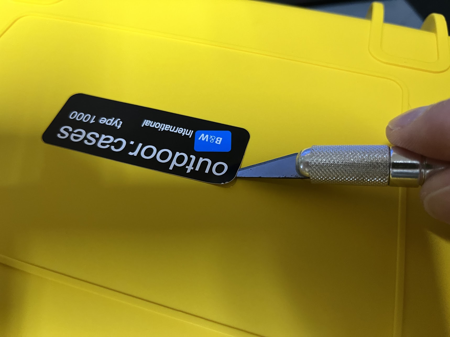
- (x1) B&W International Type 1000 Outdoor Case with SI Foam
- (x1) Silicone Elastomer 4x4 Button Keypad - for 3mm LEDs
- (x1) Diffused Blue 3mm LED (25 pack)
- (x1) Adafruit Trellis Monochrome Driver PCB for 4x4 Keypad & 3mm LEDs
- (x1) Speaker - 3" Diameter - 4 Ohm 3 Watt
- (x1) Small Lock-style Solenoid 6VDC @ 600mAh with 2-pin JST
- (x1) 1N4001 Diode - 10 pack
- (x1) TIP120 Power Darlington Transistors - 3 pack
- (x1) Through-Hole Resistors - 2.2K ohm 5% 1/4W - Pack of 25
- (x1) 5V 2.5A Switching Power Supply with 20AWG MicroUSB Cable
- (x1) Micro USB B Jack to USB A Plug Round Panel Mount Adapter
- (x1) Rugged Metal On/Off Switch with Green LED Ring - 16mm Green On/Off
- (x1) Premium Female/Male 'Extension' Jumper Wires - 20 x 6"
- (x1) Penta Angel 10pcs Double-Side Prototype PCB Universal Printed Circuit Board
- (x1) Raspberry Pi 3 Model B+
- (x1) 32GB micro SD card
- (x2) Speaker wire
- (x1) Assorted 22AWG wire spools
- (x1) Heat-shrink
- (x1) Solder
- (x1) Black spray paint
- (x1) Cable Matters 2-Pack Retractable Micro USB Cable - 2.5 Feet
- (x1) OVERTURE PETG Filament 1.75mm
- (x1) EEEEE M2 M2.5 M3 (214pcs) Metric Threaded Inserts for Plastic
- (x1) Black Nylon Machine Screw and Stand-off Set – M2.5 Thread
- (x1) Black Nylon Machine Screw and Stand-off Set – M3 Thread
- (x1) Break-away 0.1" 36-pin strip male header - Black - 10 pack
- (x1) 36-pin 0.1" Female header - pack of 5!
- (x1) UGREEN SD Card Reader
- (x1) Mounting putty
- (x1) Precision screwdriver set (6 pieces)
- (x1) HDMI cable
- (x1) Keyboard
- (x1) Mouse
- (x1) Original Prusa i3 MK3S+ kit
- (x1) Soldering iron
- (x1) Wire snips
- (x1) Wire strippers
- (x1) Needle nose pliers
- (x1) X-Acto knife
- (x1) Breadboard
- (x1) PanaVise 350 Multi-Purpose Work Center
- (x1) Helping Hands Magnifier Soldering Station
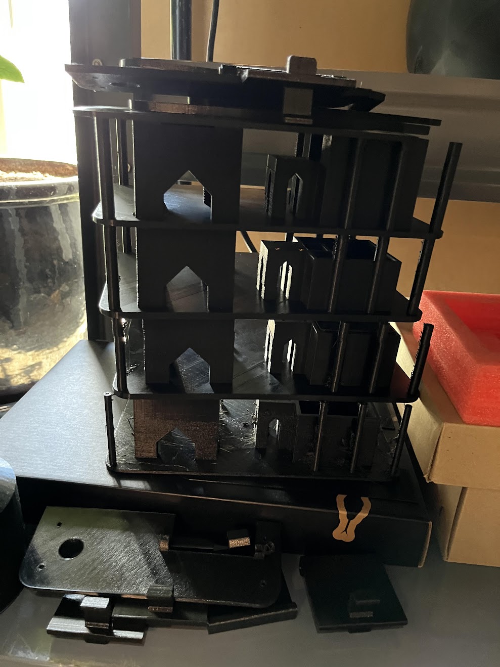
Step 2: 3D Print Parts
Get these going first, as they can take days to print on the Prusa i3 MK3S+. I made many iterations of 3D printed parts. Clearly, my trade is not in mechanical engineering. I followed the lesser known darts method of engineering. Throw a dart. If you miss your target, adjust and try again. The latest 3D models can be found on Thingiverse, complete with printer preferences.
Step 3: Initialize Raspberry Pi
While the parts are printing, start configuring the Raspberry Pi. I recommend starting with a fresh Pi, still warm, just off the kitchen window sill. If this is your first time setting up a Pi, Raspberry Pi provides a Getting Started guide. Prep the micro SD card with the Raspberry Pi OS using the Raspberry Pi Imager. Be sure to preconfigure the OS with wifi, local settings, etc. Your Pi should auto-login. This is what we want.
WARNING: I'm using a Raspberry Pi 3 Model B+. Will this project work with a different Pi? Most certainly. Will this project work with the random Pi you harvested from your inferior project. I don't know, maybe.

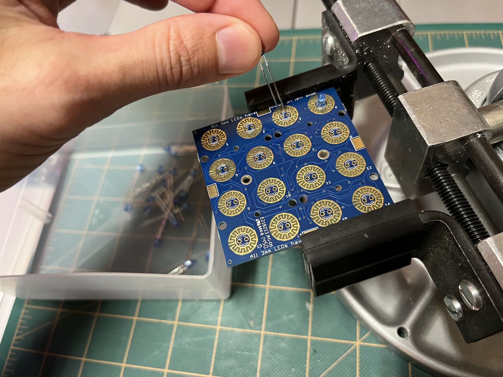
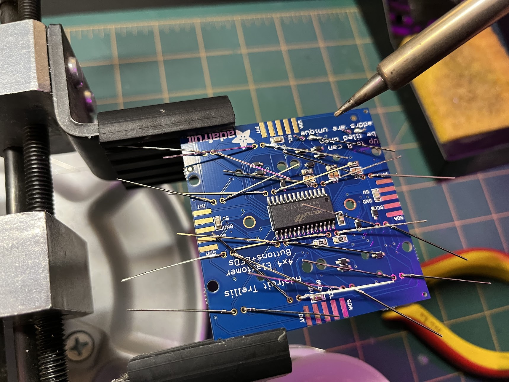
Step 4: Configure Raspberry Pi for Trellis
Because of the number of devices that need to work together, it's best to configure these one-by-one, confirming opertion of each before moving on to the next. Let's start with the Trellis board. Buttons and lights are easily rewarding. Follow Introducing Adafruit Trellis to solder the Trellis LEDs and wires. A PanaVise makes quick work of this.

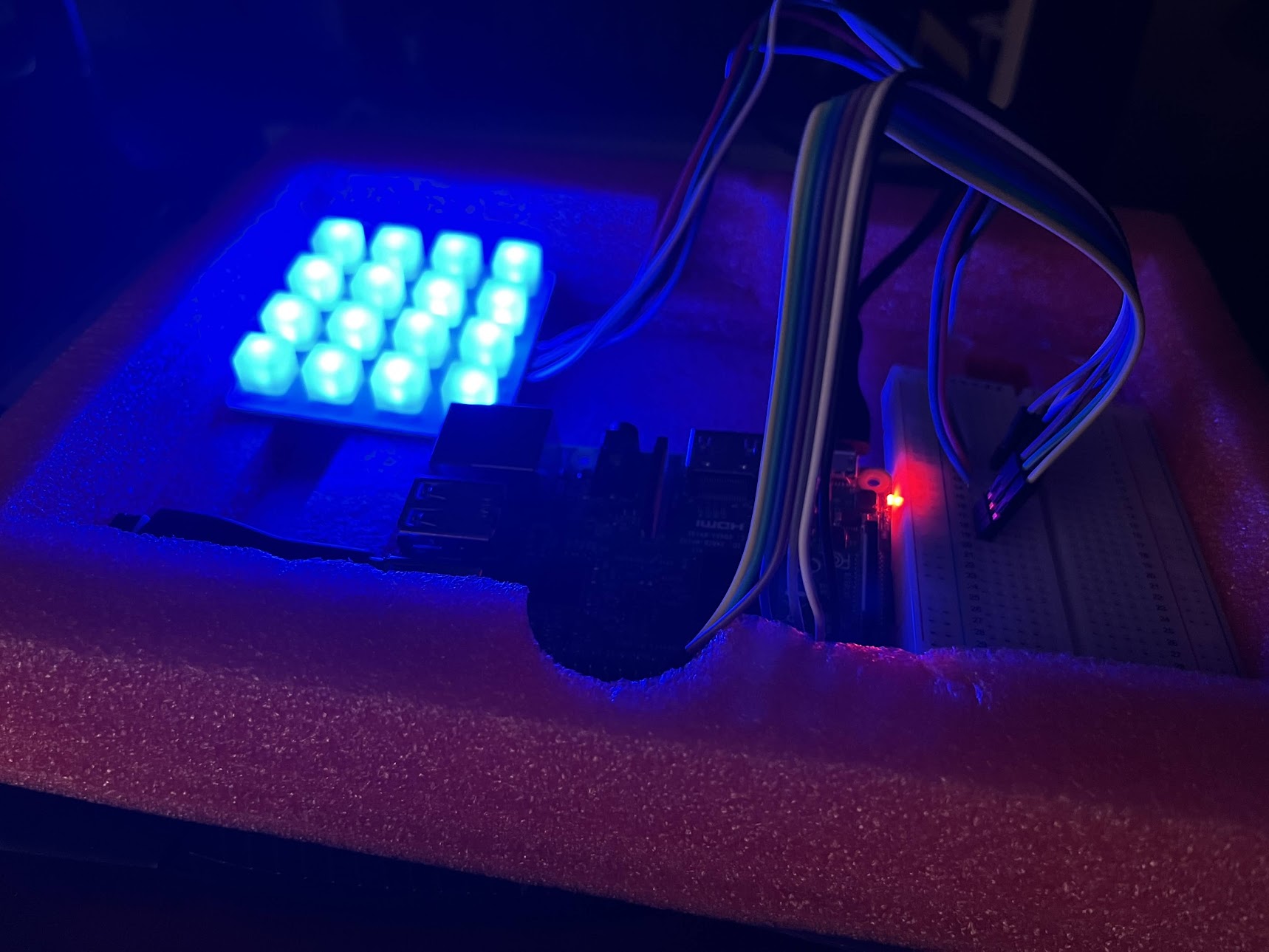
Follow Installing Blinka on Raspberry Pi to configure your Pi's I2C in prep for the Trellis. I2C will be needed to communicate with the Trellis. Confirm with the Blinka Test. Follow Python Computer Wiring and temporarily wire your Trellis and Pi. Breadboards are great for these sorts of things.

Continue Python Computer Wiring to install adafruit-circuitpython-trellis. This library is used to command the Trellis buttons and LEDs. Test your Trellis with the Full Example Code.
Step 5: Configure Raspberry Pi for Bonnet
Alone, the Raspberry Pi audio out jack is only powerful enough for headphones. To play decent audio through the 3W speaker, we need a 3W amp. The Stereo Speaker Bonnet is such an amp. Follow Adafruit Speaker Bonnet for Raspberry Pi and solder header pins to your Bonnet. Be sure to solder additional male header pins to the Bonnet's top terminals.

Take this time to solder 1ft of speaker wire to your speaker. Wire your speaker to the Bonnet and mount on the Pi. Continue to Raspberry Pi Setup to configure your Pi for the Bonnet. Select 'y' to test your system but also open up a browser to YouTube. Confirm your system audio defaults to your speaker.
Step 6: Confirm Pygame on Raspberry Pi
Pi Python should come preloaded with Pygame. Say that five times fast. We'll be using Pygame's mixer to play the soundbites. Pimoroni provides an interesting guide on how to do this. However, all you need to do is confirm the mixer can be imported with the below python command. No error is a good error.
from pygame import mixer
Step 7: Confirm GPIO Zero on Raspberry Pi
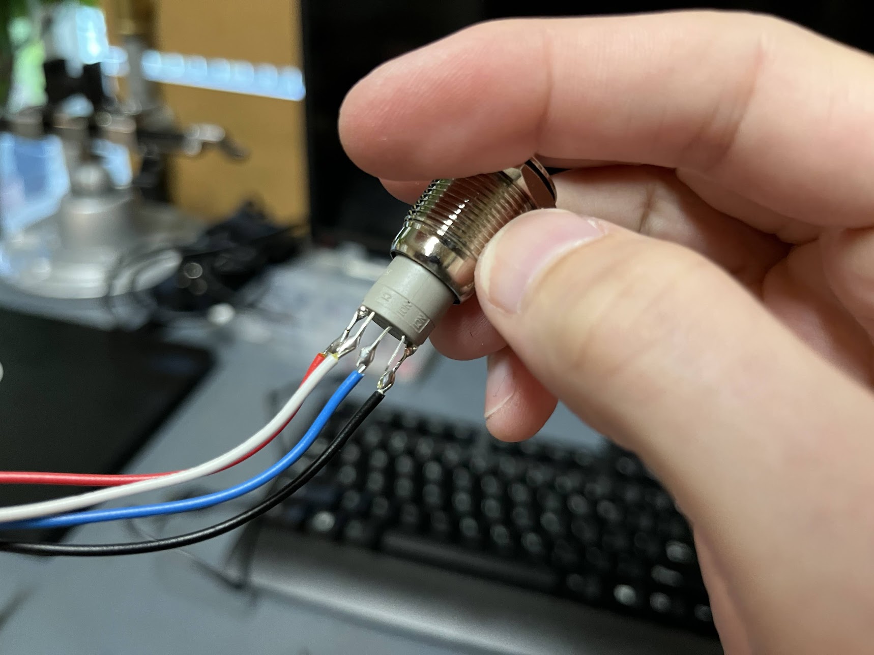
Pi Python should come preloaded with GPIO Zero. GPIO Zero is used to interact with the Pi's GPIO pins. Confirm this by following the GPIO example 2.6. Button controlled LED. Don't have a button and LED? You can use the Rugged Metal On/Off Switch with Green LED Ring. What is a switch, if not a latching button. The Switch has an internal resistor on the LED. Given the 3.3V on the Pi's GPIO, there's no need to add an additional resistor like in the example. Solder 1ft of 22AWG wire to each of the Switch terminals, leaving 'NC' wire-free. If, for some reason, GPIO Zero is not installed. GPIO Zero can be installed from 1. Installing GPIO Zero.
Step 8: Install Inserts
Ding! Parts are done printing. With the Pi mostly configured, turn your attention back to the 3D printed parts. The Base (picture) is the only part that uses inserts. Use (x8) M3 H10 inserts for the eight tallest columns. Use (x8) M2.5 H4 inserts for the eight shorter columns. Use (x4) M2.5 H4 inserts for the solenoid mount. Inserts can be installed using needle nose pliers and a soldering iron on the lowest heat setting. Holding the insert with pliers, press the insert into the appropriate slot using the soldering iron. Careful not to touch the plastic with the iron.

Step 9: Solder PCB
With the soldering iron still hot, solder the PCB. The PCB is the bridge between the Bonnet and GPIO controlled components, Switch and Solenoid, essentially the breadboard in the below picture.

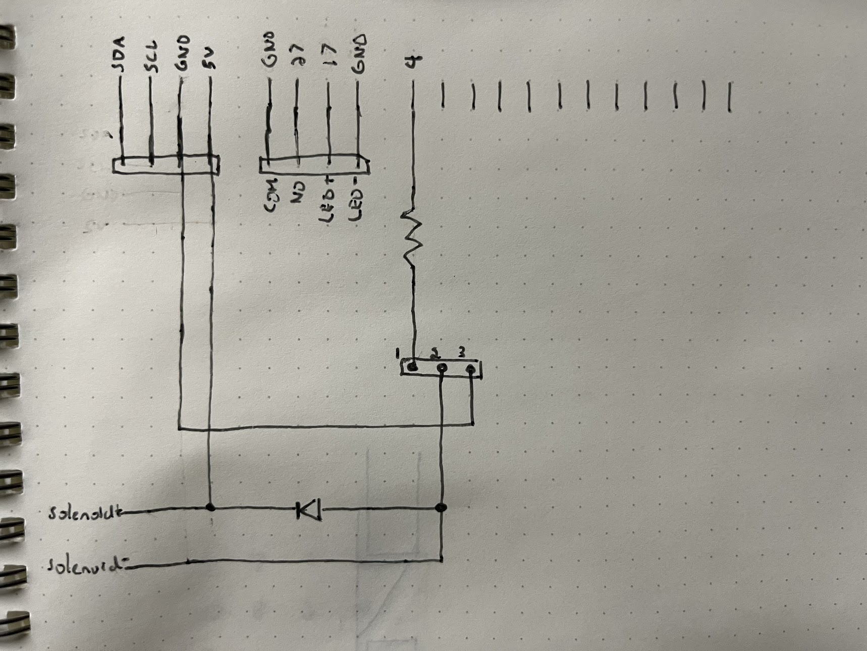
Follow the schematic to make the point to point connections. I found, in addition to the schematic, sketching the PCB layout helps (picture). I mostly used header pins and jumper wires to help with the assembly. However, I did solder the solenoid directly to the PCB and recommend you do the same. Be sure to solder the solenoid to the closest PCB corner.


Step 10: Assemble Outside
Finally! All the pieces are prepped and (mostly) tested. Let's put them together and see if they work as a whole. The box is designed such that the pieces can be assembled outside the enclosure and then inserted in the enclosure. Start with the Base. Mount the Raspberry Pi with Bonnet, PCB with Solenoid, Trellis. Insert the Drawer. Make sure the Solenoid engages, but expect to adjust the Solenoid position later. Mount the Speaker and USB Jack in the Left Panel. Mount the Switch in the Right Panel. Reference the above skematic and wire everything accordingly.


Still splayed, let's test everything and make any adjustments where necessary. Download/Clone the program content from the GitHub Repo. Place in a single folder on the Pi's Desktop. Note the file path to hbfs.py. Follow 3. Run GUI Programs on Startup With Autostart to run hbfs.py on boot. Confirm by rebooting your Pi with the following command.
sudo reboot
The Pi will take a moment to boot up. You will hear an audible pop from the speaker. The Trellis LEDs will go through their start up sequence. Pressing a Trellis button will play one of the below soundbites. The soundbite button assignment is randomly assigned after each boot. The goal is to play the soundbites in the below order to unlock the drawer. Break out a pen and paper and start mapping the correct button sequence. Doing so without a pen and paper will drive you and those around you crazy.
- Work it
- Harder
- Make it
- Better
- Do it
- Faster
- Makes us
- Stronger
- More than
- Ever
- Hour
- After
- Hour
- Work is
- Never
- Over
You may have noticed there are two "Hour"s soudbites. The discering ear will note the higher note "Hour" comes first. This is an extra challenge for the player.
With each correct button depressed, the respective LED remains illuminated. A fully illuminated Trellis will play the victory soundbite (omitted from the above video copyright reasons). At the start of the victory soundbite, the Switch LED will illuminate. Depressing the Switch at this time will engage the solenoid for 10 seconds unlocking the Drawer. Test out the Drawer a few times. Reposition the solenoid as necessary. Now's also a good time to add the prize.

Step 11: Assemble Inside
Fold the two panels over the Base and fasten in place. This is about when I noticed some tight tollerances. The USB Jack with cable comes very close to conflicting with the Raspberry Pi. The Switch comes very close to conflicting with the PCB. Squeeze everything together as best you can.


Sandwich intact, place inside the enclosure. Test again just to be sure.

Step 12: Stencil Enclosure
The pièce de résistance. Yeah, I'm no artist either, at least with paint. Use an x-acto knife to remove the sticker on top. Remove any sticky residue by hand. Position the stencil and fix in place with a little mounting putty. Cut a stencil size hole in a piece of paper. Use this to further shield the enclosure while applying a light layer of spray paint.


Here is what a heavy layer of spray paint looks like.

Step 13: Enjoy
Wrap the HBFS Box and label "Happy Mothers Day!" because you missed your friends birthday, but made it in time for Mother's Day. Ship to said friend and wait.

For more inspiration, enjoy what first inspired the HBFS Box, Adafruit's Mystery Box: Crypto Countdown Case.
Step 14: Optimize
HBFS Box 2.0. There's always room for improvement.
- Increase USB Jack clearance from the Pi.
- Increase Switch clearance from the PCB.
- Fix sticky Solenoid issue. Suspect operating the solenoid below its operational voltage is the root cause.
- Affix the Base to the enclosure somehow.